|
"Inertial Dyno"
a supplement to
The Engine Analysis Program
Part 6 (Special) (Special)
"Inertial Dyno"
After you complete the engine blueprinting, it
is time to break-in the engine. You can use the method outlined
in Part 5 of the Blueprinting articles, or have the engine run
in on a Dyno. Where do you have that done? We have been using
a dyno for several years, which was based on the Kavan Horsepower
Propellers. We finished up our NEW INERTIAL DYNO and it is now
in service. Dr. Robert Kee, a Two Stroke Researcher and Kart Racer at the
Queens University - Belfast, Northern Ireland mailed me a copy
of his published Society of Automotive Engineers paper. This
paper was how to build an inertial dynamometer. After I digested
the paper, I had to have a dyno like this. The advantages of
this type dyno are many. The engine is only run under load for
about 6 seconds (with the old dyno a run takes a MINIMUM of 2 minutes).
Acceleration of the Inertia Wheel is based on the rpm rise you
have while racing on the course. Each inertia wheel is designed
to accelerate at the rpm rise you want. Our 67 inertia wheel
is set to rise at about 6,000 rpm per second and the 45 wheel
at about 8000 rpm per second. The 21 wheel will be at about 9000
rpm per second and the 90 at about 5000 rpm per second. This
is really the most important part of the dyno, since we are testing
our engines as we will be using them in race conditions.
Let me caution you about undertaking a project
of this magnitude. I would encourage anyone who has the capability
to pull off this type project to "go for it". ONLY
if you have the manpower! Here is what it takes: a machinist
who can make precision parts and who is willing to spend the time,
an engineer who understands mathematical application and can work
with Labview (a virtual instrumentation package), an electronics
specialist is also needed to make some circuitry to control the
rev limiter and servo actuation circuit and a computer person
who understands the inner workings of the PC. The cost for computer
hardware, exclusive of the PC is about $2000. The cost for Labview
is about $1000. If you can round up these specialists, you are
off and running.
If these capabilities are not available, you
can use our dyno for your testing. We will be making the dyno
available for limited testing, and JFA Custom will offer documented
dyno runs on any engine they work on.
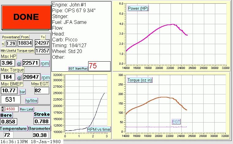
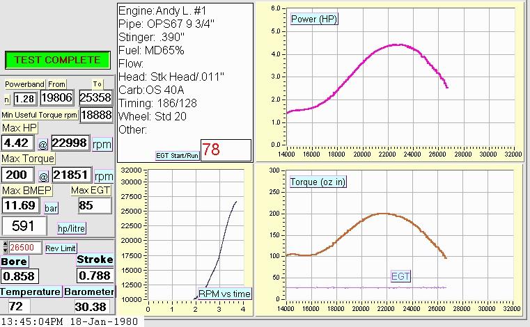
I have included 2 past dyno runs (made within
the past month) which show the output of the dyno. As you can
see, the run made on the 45 Picco and the 67 Picco have a different
format. (If you don't have a viewer to look at jpg images, I would suggest that you download LView from the Internet. It is a program that will view almost ANY image type and convert images from one format to another) With Labview the screen output and instrument design
can be easily changed. We will be continuously changing the "look"
of the instrument. As you can see the outputs are extremely revealing.
The 45 engine: I included this screen because
the engine was in a rich needle condition. The fall off at the
top end was dramatic because of this rich condition. The EGT
is a perfect indicator of whether the needle setting is correct.
By looking at the temperature of the exhaust gases in the large
portion of the pipe it is easy to see how the "needle is set".
The 67 engine:
is with a perfect needle, under ideal conditions. We feel this
engine is our current best effort and will be hard to exceed.
Some initial "Crude Testing" will be
done in the next few months, to determine the best pipes, their optimum lengths,
compression ratios, carbs, etc. This will eventually be done for all size
engines.
I hope that this short look at the new Inertial
Dyno is of interest to you. If you have specific questions, or
need time with this dyno, please write to me, Marty Davis at sales@1nitrorc.com
or to John Ackerman, owner of JFA Custom Engines at jfacustom@earthlink.net.
To download copy of the Graduate Level paper prepared by Brian Callahan on this Dyno Project - Click Here. This paper is written in Microsoft Word Format and zipped to save file size. If you don't have Microsoft Word, it will not do you any good!!!
Another FINE source for any serious
2 cycle engine builder is a book authored by Dr. Gordon Blair,
a researcher and one of the foremost 2 cycle experts in the world.
This is the ultimate technical guide available.
The Blair book & software can be purchased from SAE (Click Here
|

