|
"Engine
Blueprinting"
using
The Engine
Analysis Program
Part 1
Initial Documentation:
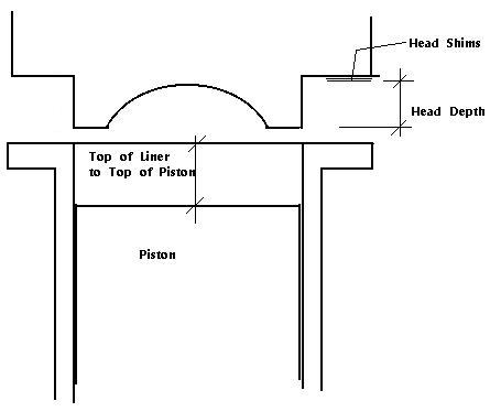
Using the Head clearance gauge that
is available from Rossi Sales of America (901)396-7485, carefully
measure the stroke of the engine. Also the head clearance of the
engine as it comes. Write down this clearance in thousandths.
Using a depth micrometer or a good set of calipers (MSC has good digital
calipers cheap) ($80.00)(800-645-7270), measure the depth of the
head from the flange on the head to the bottom of the squish band
(the depth the head protrudes into the liner). Measure WITH the
head shims in place. Add the previous two measurements together
to get the measurement of "top of the liner to top of piston".
This is a primary input item for the program. Using the
head clearance gauge
Disassemble the Engine:
Completely disassemble the engine and
inspect all parts for machining flaws. Measure the diameter (bore)
of the liner with a good set of calipers.
Measurement of the exhaust and intake
ports:
Holding the liner in your hand insert
the piston and rod into the liner and using a very high intensity
light, find the place where the piston closes EACH port. Measure
the depth from the top of the liner to the top of the piston at
each of these closing points. It will be easy to see when the
light goes out, looking through the port and moving the piston
up. It is very helpful to have an extra set of hands helping you
here, as these measurements are VERY important (ACCURACY!). The
exhaust port is usually slopped, so it is necessary to use the
light method. Input these numbers into your program and the timing
of the engine as it came stock is shown. Remember that the
boost port is the intake port(s) opposite the exhaust and the
side intakes are the transfers. After you have this documentation
it is time to decide what kind of timing you want for your engine.
I can tell you my personal preferences. But in
the end, you will have to decide what works best for you. There
are MANY considerations. How heavy is your model, what is your
driving style, etc. My models are always light
weight and I like to drive VERY close to the buoys.
I use intake ports with timing of 126
to 128 degrees on ALL my engines of all sizes. I use exhaust timing
on my .21 engines (183-185), .45 engines (185 -188), .67 engines (183-188),
.80/.90 engines (187-192). If your model is heavier,
you will want to preserve a larger part of the "low end power"
of the engine, thus LOWER the exhaust timing..
On your spreadsheet, set up a line (under the line which you
have documented the engine in stock form) to show the engine in
modified form. The intake ports will
have to be set initially. I input exactly the same measurements
on the line below the stock measurements and start changing the
top of liner to top of piston measurement, until I get the INTAKE
timing I want. The amount I have changed the top of liner to top
of piston measurement, is the amount I will have to turn off the
UNDERSIDE of the liner flange to lower it to get the intakes where
you want them. Note: Be careful that you don't lower the liner
enough that you let the bottom skirt of the piston be higher than
the bottom of the exhaust port at TDC(Sub Piston Induction). You
DO NOT want this condition as it takes away from low end power.
In some rare instances, you will have to make a liner shim to
raise the liner to get the intake timing where you want it. VERY
RARE that you have to raise the liner. This takes care of setting
the intake ports....... Next the Exhaust Port Timing and the Shape
of the Exhaust Port.
Another FINE source for any serious 2 cycle engine
builder is a book authored by Dr. Gordon Blair, a researcher and one of the foremost 2 cycle
experts in the world. This is the ultimate technical guide available.
The Blair book & software can be purchased from SAE (Click Here
|