The Engine Analysis Program
Part 3
"The Rotor or Crank Induction Assembly"
The rotor or crank induction assembly is the
heart of the engines low end power! How is this so? Consider
that the engine is "A PUMP". The efficiency
the engine shows in this role as a pump is dependent upon
a GREAT seal of the rotor disk to the backplate or the crank to
the front end. When your engine comes to you from the factory,
it has adequate clearance between the crank and the front housing
or the rotor disk and the backplate (For the sake of this tech
note I will use the crank induction and the crank fit to the front
housing in a parallel with the rotor and its fit with the back plate,
that way I won't have to repeat this every time I use an illustration
for one or the other). If you were manufacturing an engine, you
would make the interchangeability of parts easy and the fit within
a range to accommodate the widest range of machining tolerances.
We can make the fit better with the rotor assembly! The flatness
of the rotor disk and the back plate assembly can be made
MUCH better. How can you do this? By lapping the back plate assembly
on a VERY flat surface. I use a ground plate available from MSC
for about $25. Some people say they use a piece of glass (it
is really not very flat and I wouldn't suggest that you use glass).
I then apply a small amount of "Non-Imbedding Garnet"
or special aluminum lapping compound available from the Helical
Lap Company. If you want to buy a very small amount of the lapping
compound, I would suggest that you buy it from John Ackerman at
jfacustom@earthlink.net. This is the same compound that I use and it works
VERY well and does not imbed in aluminum. Be VERY careful that
you don't use diamond or some other compound that will imbed in
the aluminum, as you will continue to get lapping of all the internal
components of your engine. How then do you lap the back plate
assembly? Applying a small amount of the lapping compound on
the ground plate you pull the back plate assembly toward you in
a continuous stroke. Rotate the assembly 90 degrees and move
it forward, rotate another 90 degrees and move it toward you,
etc. This will prevent lapping in one area only, and you will
get a perfectly smooth and FLAT back plate assembly. How about
the rotor disk? If you have access to a lathe, you will want
to use a piece of bronze and face the surface flat and drill a
hole the same size as the flange on the rotor disk. Apply a small
amount of the lapping compound and start lapping, holding firm
pressure against the disk. If you don't have the capability
to lap the disk, lap only the back plate! If you lap the back plate
only it will be 100% better than it came.
Wash up the components using soap and water with
a toothbrush, being sure to get ALL the lapping compound removed.
You are now ready to fit the back plate and rotor
disk. Using a .0015 to .002 feeler gauge, place it between the
disk and back plate on ONE SIDE ONLY. Secure the rotor pin and
Loctite using #242 blue Loctite. This will give you about .0005
+/- clearance. Spin the disk and make sure it spins freely with
no evident high spots. The assembly is now ready to put back onto
the engine. Check the fit and re-lap at least 3 or 4 times per
season and you will be VERY pleased with the launchability and
power of your engine. This is the reason, when your boat stops launching
easily. The rotor fit has gone away and it needs to be re-lapped.
What about the crank induction engine. Sorry, you can't re-lap
it, you must get a new case and crank assembly. To keep the fit
perfect in the front induction (crank) engine CHANGE THE BEARINGS
BEFORE THEY FAIL!!!!!! I change my bearings during the Winter
and once before the Nationals as preventive maintenance. I have
been using a 3.5 Nova Rossi for 4 seasons and it keeps getting
better and better with no loss of seal between the crank and housing
(CHANGE YOUR BEARINGS REGULARLY!!!)
For those of you who like to have an expert do your engine work, I suggest that you send an E-Mail message
to John Ackerman owner of JFA Custom. He is the best engine builder around and has
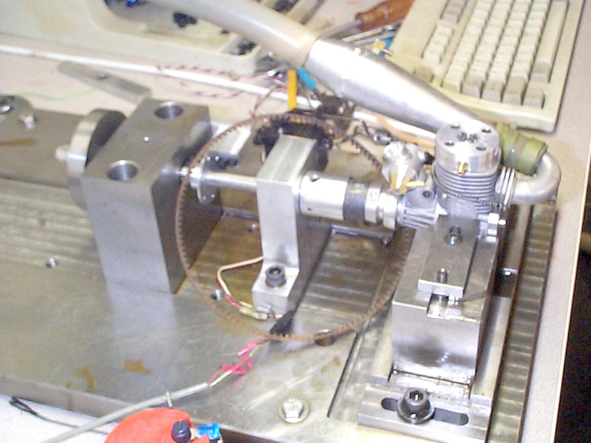
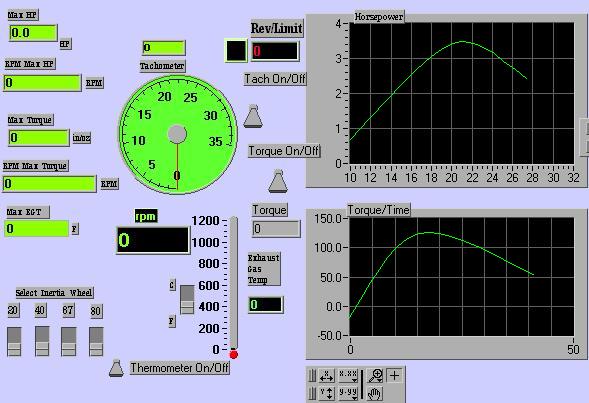
all the tools to make the job easy for him. By the way, John and I along with Norris Sparks,
Brian Callahan and Joe Kramer, are building an inertial dyno from the SAE paper
written by Dr. Kee. Here is a picture of it and a picture of the virtual instrumentation
we use to generate charts and all the readouts.
Until NEXT MONTH............... Rotor Timing.....
|